Popup headlight troubleshooting + DIY control unit
Posted: Fri May 09, 2014 1:08 pm
This is an account of my efforts to diagnose and replace a dead popup headlight controller.
It is not all original work (see below) but it should provide a step-by-step guide to anyone else needing to do this for the first time.
My googling found a lot of discussion about popup headlight problems, but the great majority were either too vague (hit it, spray it with WD40, replace it with a good one, etc) or referred to replacement parts from a firm that was either on some other continent or had gone out of business or both.
The two really useful sources that I found were -
'Roll yer own Popup Headlight Control Module' by john82q on the Australian Katana site
http://members.suzuki-katana.net/viewto ... 807#p25966
where the headlight wiring has been analysed, but unfortunately the work doesn't yet seem to have progressed to a working replacement controller, and
'Popup control unit' by callyboy (Pete) on here
http://www.katanaownersclub.co.uk/forum ... =28&t=5906
who gives a relay-based controller diagram sourced from a japanese contact.
With this information to hand, here goes...
Step 1 - check the operation of the motor and limit switches.
Before worrying about the controller it seems worth checking that the motor itself is working correctly.
Remove the fairing so that you can get to the motor and wiring.
Unplug the motor connector.

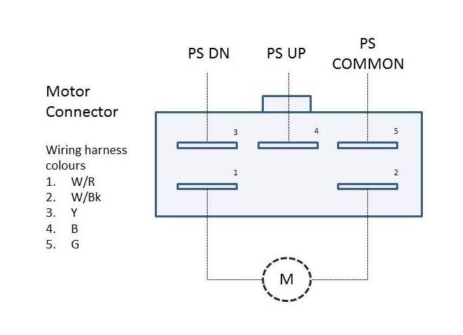
Test the motor by connecting pin 1 to +12v and pin 2 to ground.
The motor should run and the headlight should cycle up and down continuously.
Test the limit switches. There are diodes built into the switches so you cannot just slap a continuity tester on there unless you make sure that the common connection (pin 5) is positive with respect to the switch outputs.
So, either connect pin 5 to +12v and a test bulb from either pin 3 or 4 to ground, or use a multimeter with a 'diode test' range.
Now as you manually raise and lower the headlight using the red knob below the motor you should see pin 3 go open circuit when the headlight is fully down, and pin 4 go open circuit when fully up.
Hopefully all is good. If not you need to fix the motor before continuing. There are other posts on this.
Step 2 - replacing the control unit.
This is where the fun begins.
Remove the original broken/dead control unit from its hiding place below the headlight frame.
In the Suzuki workshop manual (page 9-12) there is a complicated table showing the resistance that you should measure between all of the control unit pins. In my case everything was either open or short circuit, but then I already knew the controller was dead so that was no great help.
Time to replace the control unit.
I decided to build the japanese relay circuit from Pete as it is simple and uses easily-obtainable parts.
How can a complex box of electronics be replaced by two relays and two diodes? An inspired piece of elegant design I guess. Relay logic is 1930's technology but simple and reliable. No specialist components needed. Any old 1A 50V diodes and minature SPDT 10A relays will do.
Component cost was about £8 using ebay.
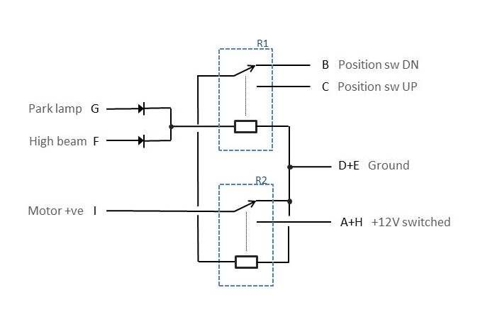
Here is the circuit as given and my redrawing of it -


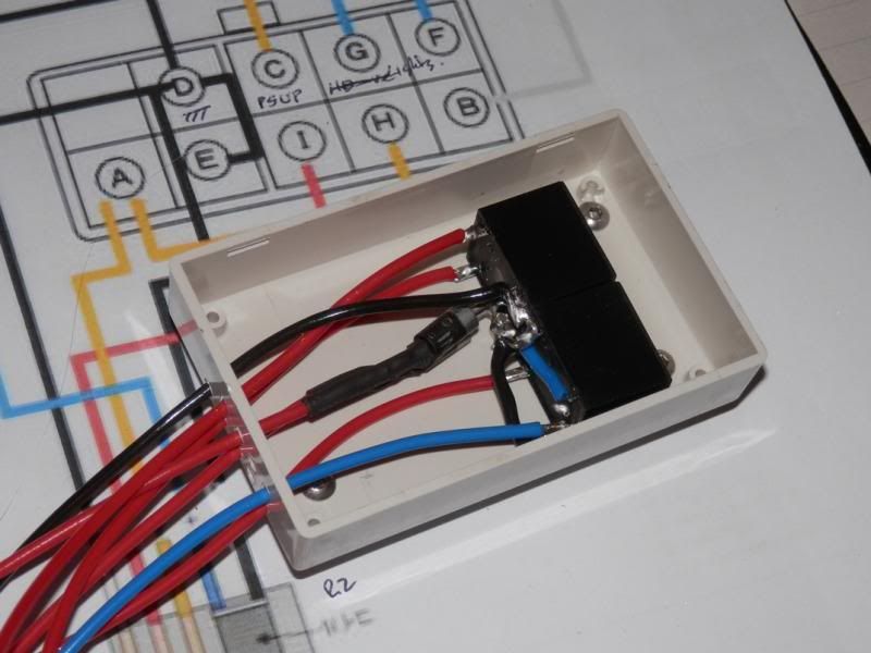
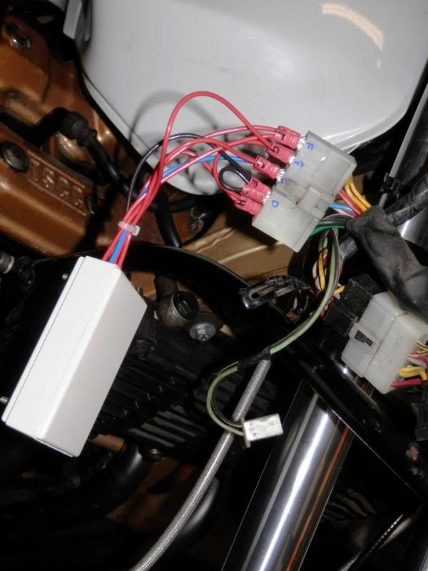
I just made up a prototype using flying leads and crimp connectors without trying to reuse the original control unit box and connector. If you can painstakingly take apart the original encapsulated insides of the suzuki box (hammer, chisel, dremel, heat, toxic chemicals) then you could build a very neat replacement.
The only issue I had was that the cheapo crimp terminals I had are a rather loose fit in the original harness connector.


Ok, wire it up, plug it in and - it works!
Everything seems to function correctly, on, up, off, down, beer time.
Note.
The two diodes in the circuit form an OR gate so that the motor will activate when either the headlight or sidelight (park lamp) is on. However, when I checked I found that on my bike the sidelight is on even when the headlight is on, so the diodes could be deleted and the coil of R1 connected directly to the sidelight connection (pin G). Maybe this differs between different models though.
As I said, this was all thanks to the work of others but it may hopefully be of use if you are trying to get your head round how to fix it.
It is not all original work (see below) but it should provide a step-by-step guide to anyone else needing to do this for the first time.
My googling found a lot of discussion about popup headlight problems, but the great majority were either too vague (hit it, spray it with WD40, replace it with a good one, etc) or referred to replacement parts from a firm that was either on some other continent or had gone out of business or both.
The two really useful sources that I found were -
'Roll yer own Popup Headlight Control Module' by john82q on the Australian Katana site
http://members.suzuki-katana.net/viewto ... 807#p25966
where the headlight wiring has been analysed, but unfortunately the work doesn't yet seem to have progressed to a working replacement controller, and
'Popup control unit' by callyboy (Pete) on here
http://www.katanaownersclub.co.uk/forum ... =28&t=5906
who gives a relay-based controller diagram sourced from a japanese contact.
With this information to hand, here goes...
Step 1 - check the operation of the motor and limit switches.
Before worrying about the controller it seems worth checking that the motor itself is working correctly.
Remove the fairing so that you can get to the motor and wiring.
Unplug the motor connector.

Test the motor by connecting pin 1 to +12v and pin 2 to ground.
The motor should run and the headlight should cycle up and down continuously.
Test the limit switches. There are diodes built into the switches so you cannot just slap a continuity tester on there unless you make sure that the common connection (pin 5) is positive with respect to the switch outputs.
So, either connect pin 5 to +12v and a test bulb from either pin 3 or 4 to ground, or use a multimeter with a 'diode test' range.
Now as you manually raise and lower the headlight using the red knob below the motor you should see pin 3 go open circuit when the headlight is fully down, and pin 4 go open circuit when fully up.
Hopefully all is good. If not you need to fix the motor before continuing. There are other posts on this.
Step 2 - replacing the control unit.
This is where the fun begins.
Remove the original broken/dead control unit from its hiding place below the headlight frame.
In the Suzuki workshop manual (page 9-12) there is a complicated table showing the resistance that you should measure between all of the control unit pins. In my case everything was either open or short circuit, but then I already knew the controller was dead so that was no great help.
Time to replace the control unit.
I decided to build the japanese relay circuit from Pete as it is simple and uses easily-obtainable parts.
How can a complex box of electronics be replaced by two relays and two diodes? An inspired piece of elegant design I guess. Relay logic is 1930's technology but simple and reliable. No specialist components needed. Any old 1A 50V diodes and minature SPDT 10A relays will do.
Component cost was about £8 using ebay.
Here is the circuit as given and my redrawing of it -


I just made up a prototype using flying leads and crimp connectors without trying to reuse the original control unit box and connector. If you can painstakingly take apart the original encapsulated insides of the suzuki box (hammer, chisel, dremel, heat, toxic chemicals) then you could build a very neat replacement.
The only issue I had was that the cheapo crimp terminals I had are a rather loose fit in the original harness connector.


Ok, wire it up, plug it in and - it works!
Everything seems to function correctly, on, up, off, down, beer time.
Note.
The two diodes in the circuit form an OR gate so that the motor will activate when either the headlight or sidelight (park lamp) is on. However, when I checked I found that on my bike the sidelight is on even when the headlight is on, so the diodes could be deleted and the coil of R1 connected directly to the sidelight connection (pin G). Maybe this differs between different models though.
As I said, this was all thanks to the work of others but it may hopefully be of use if you are trying to get your head round how to fix it.